 Looking at the motor PCB on the Panasonic drive, we can see 5 control lines
at the upper left corner. These lines connect in a semi-circular pattern,
which is:
Looking at the motor PCB on the Panasonic drive, we can see 5 control lines
at the upper left corner. These lines connect in a semi-circular pattern,
which is:
Although 5.25" HD (1.2M) PC drives can read DS/DD media, they do so at 300kbps, which is non-standard for this media type, and has two disadvantages. (1) The disk images created will indicate a non-standard 300kbps data rate. and (2) it's hard enough to get a PC to read single-density - some that can do it at 250kbps cannot do so at 300kbps.
Fortunately, many 5.25" HD drives are fairly easy to modify to operate at 300rpm and 250kbps. This page describes how you can add a switch to a 5.25" HD drive to allow it to operate at either 300 or 360 rpm. The drive shown is a Panasonic JU-475 which is a very common HD drive used in PCs, however the techniques shown here can be applied to many other drives.
Click any photo to view a large high-resolution image.
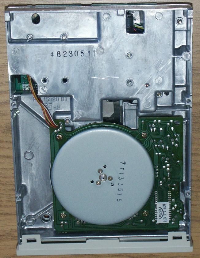
Most HD drives use a direct drive motor which is mounted on a separate circuit board located under the drive. This is easily identified by the large flywheel. Most of these motor units are capable of operating at either 300 or 360rpm, and the speed is selected by a control line. Some HD drives actually support 300rpm operation via a speed select line on the interface, but many PC drives simply have the speed select permanantly tied to "360 rpm".
The modification described here adds a switch which forces the motor speed select line to the "300 rpm" position. When disabled, the switch reconnects it to the main drive PCB and the drive operates as it normally would.
Looking at the motor PCB on the Panasonic drive, we can see 5 control lines
at the upper left corner. These lines connect in a semi-circular pattern,
which is:
      O - Motor ON     (White)
      O - +5V supply   (Red)
     O -- Speed select (Yellow)
  O O --- +12v supply  (Orange)
   \----- Ground       (Black)
The connections on your drive may be different, so our first order of business
is determine which wire is the speed select signal.To identify the Motor-ON signal, you will need to be able to probe these connection with the drive operational. You will need to provide power and floppy cable from your PC while the drive is resting upside down on a table.
Begin by measuring the signals without the drive operating. You should see only one signal at +12v, which means it's the 12v power supply. The remainder should all be at 0V or somewhere near +5v. Carefully note the state of each signal. We will determine which is which by a process of elimination.
If only one signal is at 0V, that MUST be ground. If only one signal is at +5V that is probably the +5 supply (some drives don't use a +5 supply on the Motor) - if your drive has only 4 wires this may be the case.
Start the drive, you can do this with the Align/test function of my ImageDisk program, or a simple DOS format command will do (in either case you will need to have a disk in the drive). Check the signals while the motor is running - one signal should be in a different state than it was when the motor was stopped. This will be the Motor ON signal.
You should now know two signals (+12 supply and Motor ON) - this leaves three signals which are unknown. Of these one MUST be at 0V (Gound) and one Must be at 5V (+5 supply). So you will see either 1 at 0V and 2 at +5V, or 2 at 0V and 1 at +5V. Whichever one is the "odd man out" is NOT the Speed select line - now we are down to two wires.
Look at the drive PCB - if one of the two remaining signals goes to a thicker trace than the other, it is likely Ground or +5. Once you have made a "guess" as to which is the speed-select line, cut it at a position where you can easily connect both pieces back together if necessary. Try the drive - If the motor does not run, you guessed wrong - fix the broken wire and guess again. If the motor does run, it should run at either 360 or 300 rpm.
Using a 470 Ohm resistor, connect the cut wire from the motor PCB to whichever logic level was NOT being presented by original connection. Ie: If it was at +5V, connect it via the resistor to ground. If it was at 0V, connect it via the resistor to +5V. Try the drive - If you have the right line, the motor should now be running at 300rpm (You can use the TestRPM function of ImageDisk to confirm this).
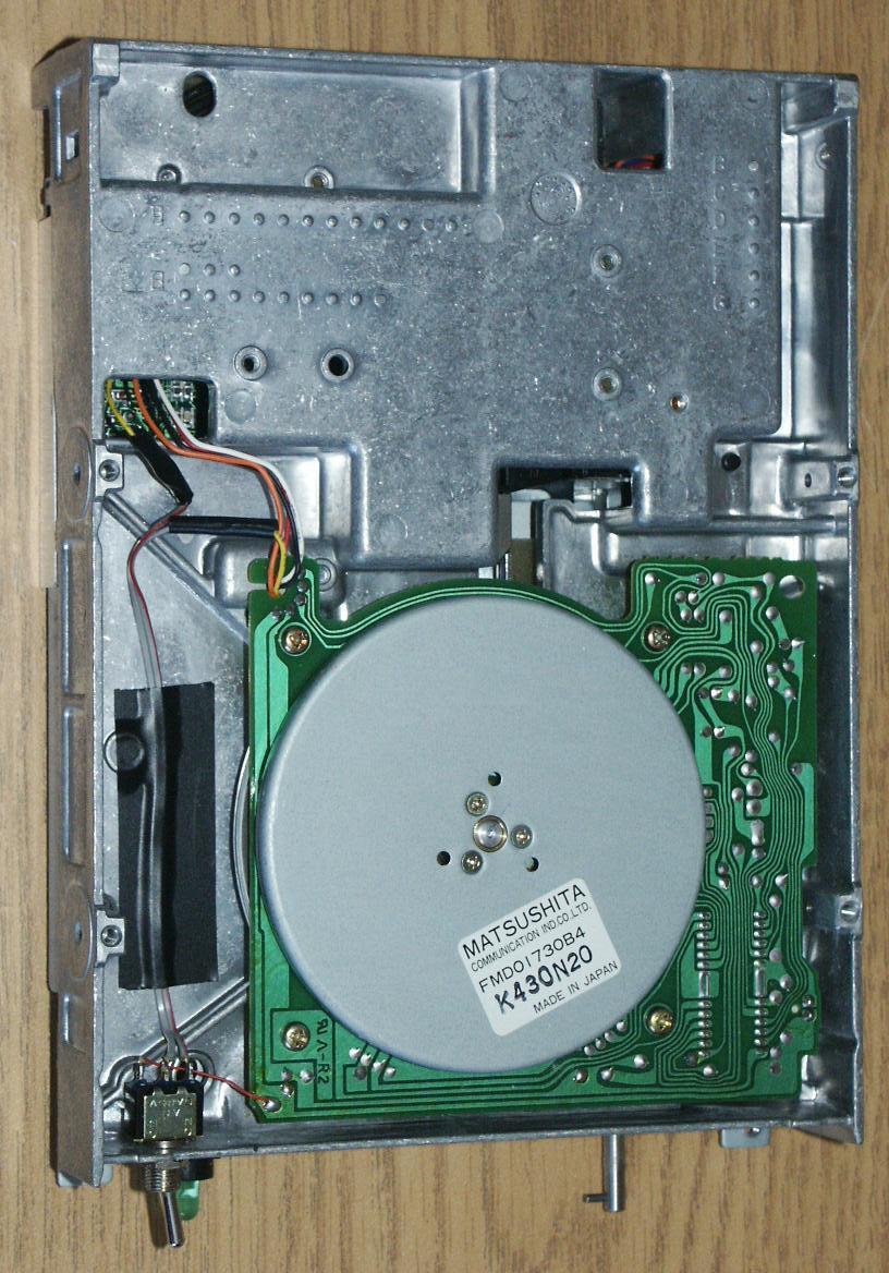
 Where you mount the switch will depend on your drive. For the panasonic drive
there is a spot at the front of the metal frame where I drilled a hole for a
panel mount toggle switch. In this photo, you can also see that the yellow
speed select wire has been cut.
Where you mount the switch will depend on your drive. For the panasonic drive
there is a spot at the front of the metal frame where I drilled a hole for a
panel mount toggle switch. In this photo, you can also see that the yellow
speed select wire has been cut.
For most drives you will need to remove the faceplate. This will vary with the particular drive, however usually the load-lever pulls straight out from the front, and two or more screws on the top or bottom of the drive secure the faceplate. There may also be mounting clips. The Panasonic drive has two screws on the top, and two clips on the bottom. With the Panasonic drive you also have to rotate the load lever to the loaded position to get the shaft key to clear the bezel - the easiest way to do this is to put a scratch diskette in the drive.
 Install the SPDT switch, and connect it as follows:
(note) - The logic level connected to the second outside lug of the switch must the the opposite to the logic level presented on the wire from the main PCB. If the main PCB presents +5v, connect the third lug to ground.
In this photo, you can see that I used a small piece of tape to secire the wires to the drive chassis. You can also see that I obtained Ground for the third switch lug from a nearby point on the motor PCB (I simply traced the PCB traces from the ground connection).
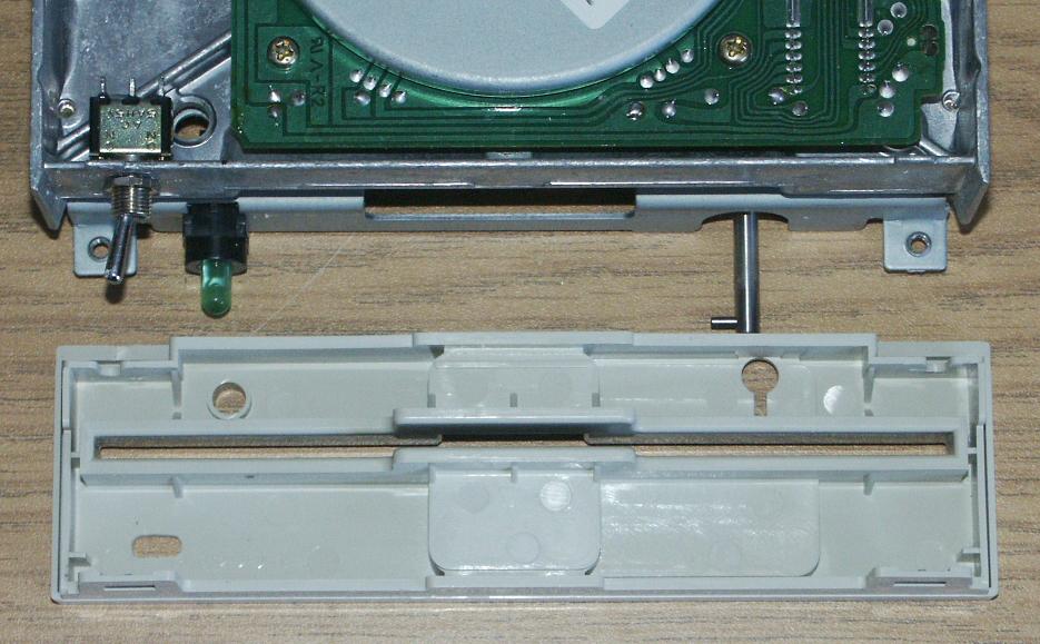 If you mounted the switch to the metal drive chassis as I did, you will need
to provide a hole or slot for it to be operated from the front panel. I
determined the location for the slot by coating the head of the switch toggle
with ink and then sliding the faceplate into position until it touched the
toggle. Repeat with the switch in the other position and you will have the
two extents of it's travel marked. I used a dremel tool to cut the slot.
If you mounted the switch to the metal drive chassis as I did, you will need
to provide a hole or slot for it to be operated from the front panel. I
determined the location for the slot by coating the head of the switch toggle
with ink and then sliding the faceplate into position until it touched the
toggle. Repeat with the switch in the other position and you will have the
two extents of it's travel marked. I used a dremel tool to cut the slot.
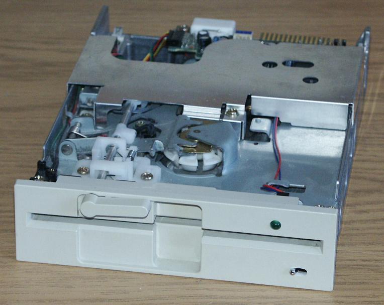 Replace the faceplate and load lever, and you are done. Now the drive can be
switched to operate as a normal HD drive at 360 rpm and 300/500 kbps, or as a
DS/DD 80-track drive operating at 300 rpm and 250kbps.
Replace the faceplate and load lever, and you are done. Now the drive can be
switched to operate as a normal HD drive at 360 rpm and 300/500 kbps, or as a
DS/DD 80-track drive operating at 300 rpm and 250kbps.
Setting the switch to 300 rpm will allow you to record DS/DD images at the proper data rate, and in many cases will improve single-density operation.