 Begin with an ISA bus connector from a dead PC mainboard - this is the correct
spacing for the 50 pin 8" drive, but it is 62 pins, which is too long for the
8" drive. Cut down to 50 pins.
Begin with an ISA bus connector from a dead PC mainboard - this is the correct
spacing for the 50 pin 8" drive, but it is 62 pins, which is too long for the
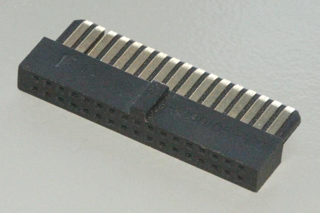
8" drive. Cut down to 50 pins.In order to be able to read and write a wide variety of diskette formats with ImageDisk and TeleDisk, you need to be able to connect a variety of drives to your PC. Here are a few tips on how to accomplish this:
Click any photo to view a large high-resolution image.
Any PC that can handle HD (High Density) drives should be able to communicate with an 8" drive - the main problem is that no off-the-shelf PC cables exist to connect the 34 pin controller connector to the 50 pin connector on the 8" drive. This section describes a simple adapter that allows connection of an 8" drive to a standard PC 5.25" drive cable.
Begin with an ISA bus connector from a dead PC mainboard - this is the correct
spacing for the 50 pin 8" drive, but it is 62 pins, which is too long for the
8" drive. Cut down to 50 pins.
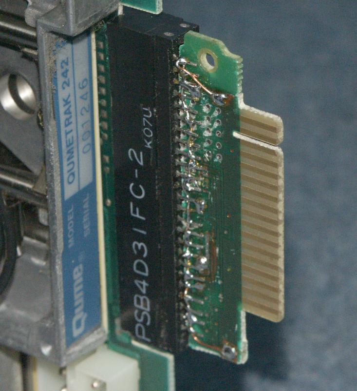
Salvage a 34 pin edge connector from a dead 5.25" drive - look for one which has a "ground plane" connecting the odd numbered pins. Leave about 1/2 inch of board under the connector, remove components and carefully cut tracks to insure that the even number pins are isolated from the remainder of the board.
Scrape away the solder mask to bare the ground plane. Position the "board" between the rows of pins on the 50 pin connector, centered from each end with the ground plane against the odd numbered pins of the 50 pin connector. Solder the odd pins to the ground plane and add wire extensions to insure that all 25 pins are joined together.
 Using 30 gauge "wire-wrap" wire, and being careful to only solder to
the very inner end of the "fingers" on the 34 pin edge connector,
connect the even numbered pins according to the pinout below.
Using 30 gauge "wire-wrap" wire, and being careful to only solder to
the very inner end of the "fingers" on the 34 pin edge connector,
connect the even numbered pins according to the pinout below.
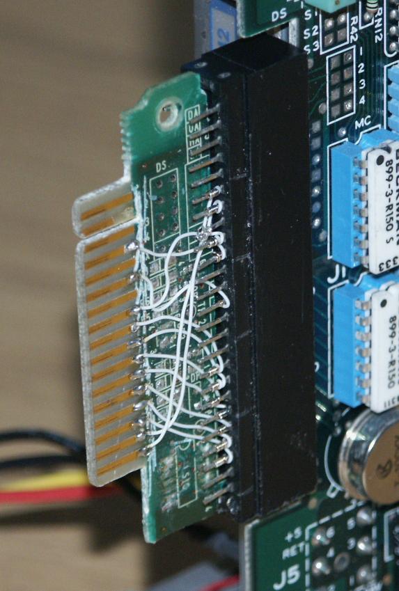
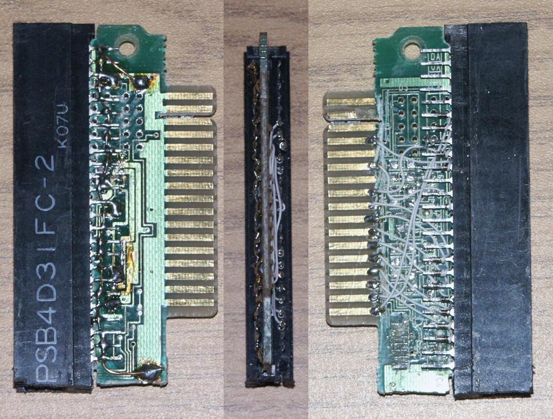
You will now have an adapter which can be plugged onto an 8" drive and allows you to connect to a standard 34 pin 5.25" PC cable. MAKE SURE the pins line up correctly on the 8" drive connector - The cut down connector has one end open, and therefore CAN be installed with the pins out of alignment.
NOTE: This pinout connects DS1 on the PC (the standard for both drive A or B with a twisted cable) to DS0 on the 8" drive. You can leave the 8" drive jumpered as Drive-0, and connect it as either A or B at the apropriate position on the PC cable.
Here is a more detailed view.
PC(34p)   8"(50p)   Description
            2        TG43                 (see below)
    8      20        Index
    12     26        DS1(PC) -> DS0(8")
    16     18        Motor ON/Head Load
    18     34        Direction            (see below)
    20     36        Step
    22     38        Write Data
    24     40        Write Gate
    26     42        Track 0 detect       All Odd numbered
    28     44        Write Protect        pins are GROUND
    30     46        Read Data
    32     14        Side1 Select
    34     12        Ready
Some 8" drives require a signal called "TG43" which indicates that
the drive is positioned to a cylinder greater than 43. This is used
to reduce the write current on inner cylinders.
The diskette controller in the IBM PC does not provide this signal,
which causes write problems on the inner tracks of some 8" Drives.
There are several possible solutions:
Some drives do not require TG43. Examine the control board on your drive. If Pin 2 of the 50 pin interface connector is not connected, then your drive does not require TG43. If it is connected, the drive MAY require TG43 - it may also be a jumper selectable option, please consult your drive documentation.
Since TG43 is used only during WRITE operation, you will be able to read 8" disks. Writing may fail or be unreliable on inner tracks.
You can also try tying TG43 permanently LOW or HIGH ... One or the other may allow you to create disks which although not correct, MAY be readable and can be copied on the destination computer to create correctly written disks.
The floppy control chip in the PC provides TG43 and DIRECTION on the same signal. When moving the head this signal means DIRECTION, when writing, the signal means TG43 (reduce write current).
IF your disk controller does not "remove" TG43 from pin 18 of the interface during write, and IF your drive is compatible with the multiplexed signals, then you MAY be able to provide TG43 to your drive just by connecting both Pins 2 (TG43) and 34 (DIRECTION) of the 50 pin 8" interface to pin 18 (DIRECTION) of the PC interface.
Note that although this works with some drives, it does not meet the floppy interface standard which requires these signals to be driven separately. Some drives will not work in this configuration.
If you are using my ImageDisk program, it provides the capability to generate the TG43 signal from the parallel port. Please refer to the ImageDisk documentation for details.
If all else fails, you can control the TG43 signal with a toggle switch connected to interface pin 2 of the 8-inch drive. ImageDisk has an option to make it pause for manual TG43 control when the signal needs to change.
If you are only adding extra drives infrequently, the simplest solition is to just pull the cover off your computer, unplug the internal drive(s) from the floppy controller, and plug in a cable to the external drives.
If you plan to use external drives a lot, it may make sense to construct a neater and more rugged solution. This section describes a set of custom drive cables which allows external B: drives to be removable, and to co-exist with an internal A: drive without having to disassemble the computer.
 Here is the cable inside the PC. It begins with the connector to the PC
floppy controller at the lower-right, and continues to the internal floppy
drive connectors at the top, and on to a female 37-pin D-type connector for
the external drives on the left end (mounted on a slot backplate). This
particular cable has connectors for either a 3.5" or 5.25" internal drive,
however you need provide only the one you will be using,
Here is the cable inside the PC. It begins with the connector to the PC
floppy controller at the lower-right, and continues to the internal floppy
drive connectors at the top, and on to a female 37-pin D-type connector for
the external drives on the left end (mounted on a slot backplate). This
particular cable has connectors for either a 3.5" or 5.25" internal drive,
however you need provide only the one you will be using,
It is important that the external connector be at the end of the cable. All floppy drives should be "in line" on the cable. If the external connector were placed in the middle, we would have a "branch" when the external drives are plugged in, which would be incorrect.
Note that this connector differs from a standard PC floppy cable in that it has the twist in the cable both before and after the middle connector. This has the effect if placing Drive-A in the middle of the cable, and Drive-B at the end of the cable. This is important because we want the internal drive to be A, so that the system has a normal/bootable floppy drive when the external drive is not attached.
 Here is the cable between the PC and the external drive. It is simply a male
37-pin D-type connector and a standard 5.25" floppy disk connector. This allows
direct connection to an external 5.25" drive, or an 8" drive using the adapter
described above. I use this adapter when I need to
connect an external 3.5" drive. If you prefer, you can simply put a 3.5"
compatible connector on the cable next to the 5.25" one. If you make your internal
drive a 3.5" 1.44MB drive, you may not even need an external 3.5" drive.
Here is the cable between the PC and the external drive. It is simply a male
37-pin D-type connector and a standard 5.25" floppy disk connector. This allows
direct connection to an external 5.25" drive, or an 8" drive using the adapter
described above. I use this adapter when I need to
connect an external 3.5" drive. If you prefer, you can simply put a 3.5"
compatible connector on the cable next to the 5.25" one. If you make your internal
drive a 3.5" 1.44MB drive, you may not even need an external 3.5" drive.
When assembling both cables, put pin-1 of the cable (normally marked with a RED stripe) in the pin-1 position of the connectors. Pins 35-37 of the 37 pin connectors will be unconnected.
Before installing, perform a visual check. Plug the connectors together and follow the pin-1 signal from the FDC connector all the way to the external drive connector and insure that it ends up in the right place. If you have test equipment, you may want to "buzz out" the electrical connections through the combined cables and confirm that they are correct.
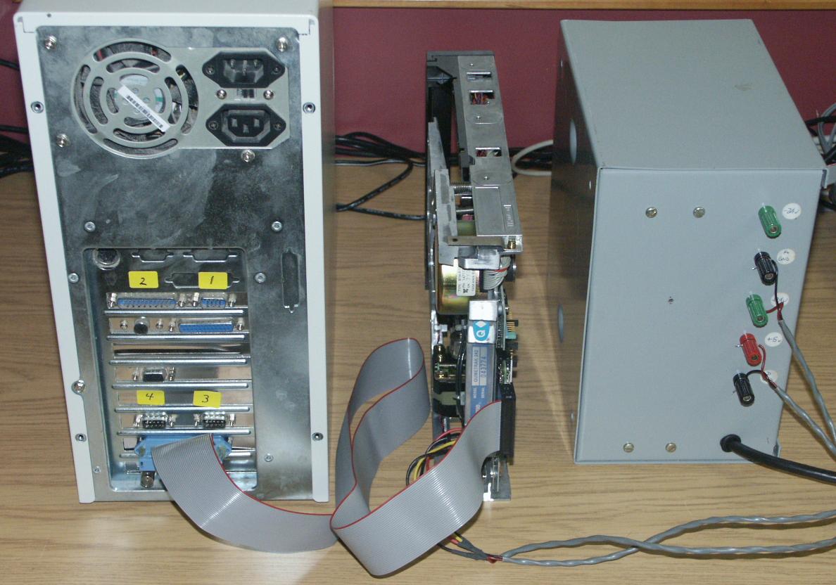 Here is the complete installed system demonstrating a connection to an external
8" drive using the cables and adapter described above. The large box to the
right of the drive is a +5V/+24V power supply required by the 8" drive.
Here is the complete installed system demonstrating a connection to an external
8" drive using the cables and adapter described above. The large box to the
right of the drive is a +5V/+24V power supply required by the 8" drive.
For clarity, I removed all other cables before taking the photo.
To work properly, a floppy drive system should have terminating resistors (usually 150 Ohm) installed in the LAST drive on the cable only. This causes a slight wrinkle in our design, because the terminating resistors should be in the external drive when it is connected, and in the internal drive when no external drive is connected.
The most correct way to use this system would be to remove the terminating resistors from the internal drive, and to install them in the external drive. You should also construct a "terminator plug" which has the terminating resistors which would be installed in the external drive connector when the external drive is NOT connected.
Most modern PC 3.5" drives (and some 5.25" ones) do not provide the standard removable 150 Ohm termination. Instead, they use terminating resistors of a higher value (often 1K or more) which are "always on" for each drive on the cable. This is a compromise, but it works most of the time, and means that people generally no longer have to worry about configuring drive termination in modern PCs.
If your internal drive is a modern drive with this type of termination, you can probably make do by installing the termination in your external drive, and leaving the internal drive "as shipped". When the external drives are attached you will have slightly higher loading due to the internal drive termination, but in most cases this will work OK. If you do have problems, try experimenting with high value termination resistors in the external drive (220 or 330 ohm).
As with any transmission system, the longer the cables, the more noise will be introduced, and the higher the possibility of errors. Keep cables as short and direct as possible.